Materials and Manufacturing
This page summarizes 3D-printed verification and the manufacturing process.
3D-Printed Verification
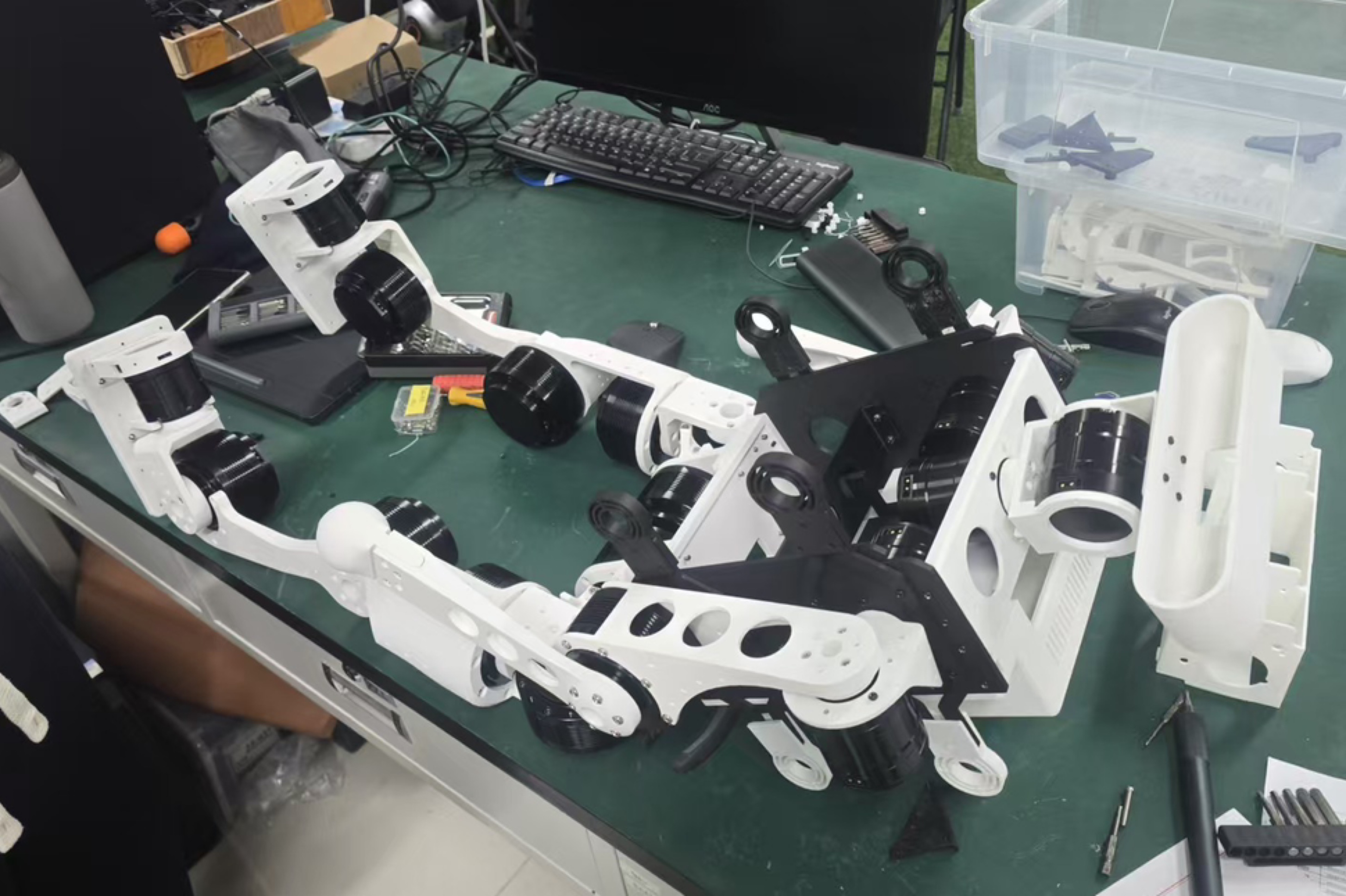
Because machining takes a relatively long time and is expensive, during the validation stage we used 3D-printed structural parts and assembled the full robot to verify whether the joint range of motion, chest internal layout, and similar design choices were appropriate. Only after confirming that the mechanical design was acceptable did we send the parts out for machining. One thing to note is that 3D printing cannot verify threaded holes, because print precision is not sufficient to reproduce threads directly. Through holes in 3D-printed parts also tend to come out slightly undersized, but screws can usually still be driven through with force. We used a Bambu Lab printer. PLA or PETG both work for regular parts, and TPU is recommended for soft components.
Machining
We used 6061 aluminum alloy. In reality, machinists have much more practical experience in this area than we do, and our understanding is only partial. A few points still matter. First, add more fillets where possible, because they are easier to machine. Second, avoid closed structures, because cutting tools always machine from the outside. Third, if a part can be designed as a flat plate, try to make it a flat-plate structure, because it may then be produced by laser cutting instead of CNC machining. Finally, remember to perform proper surface finishing after machining.
Internal Corners
Sharp internal corners cannot be milled directly. If a part is designed with a sharp internal corner, the cylindrical shape of the milling cutter and its rotary cutting motion will always leave an internal fillet with a radius equal to the cutter radius.
Design consideration: keep internal corners as consistent as possible. All internal corner radii should be no smaller than the radius of standard cutters, and should preferably use common values to avoid unnecessary tool changes.
Deep Cavities and Deep Slot Blind Areas
Insufficient tool length: when the cavity depth exceeds the cutting-edge length of the tool, the tool holder will interfere with the top surface of the workpiece, making the bottom impossible to machine. Insufficient tool rigidity: even if the cutting edge is long enough, an excessively large depth-to-diameter ratio causes severe vibration and elastic deformation in slender tools, which can lead to taper in the machined hole.
Design consideration: avoid deep and narrow structures. Keep slot depth and slot width in a reasonable ratio, or redesign the feature as a through-slot.
Clamping Interference Blind Areas
This is a process blind area caused by the milling machine fixturing setup. The regions blocked by vises, pressure plates, magnetic chucks, and other fixtures cannot be machined directly.
Tool Entry and Exit Space
When milling a closed cavity, if ribs or bosses block the cavity entrance, the cutter cannot plunge vertically into the cavity.
Design consideration: reserve a plunge hole or an arc-tangent tool-entry channel at the cavity edge, with a diameter larger than the cutter diameter.