URDF
This section explains the steps for exporting a URDF model from the mechanical model.
Exporting URDF from SolidWorks
Step 1: Preparation and Plugin Installation
Download the plugin: get the sw_urdf_exporter plugin from the ROS Wiki. Install the plugin: run the installer after downloading it. Once the installation is complete, restart SolidWorks.
Step 2: Model Preprocessing
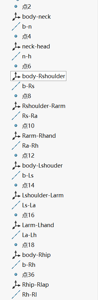
Open an assembly model and define reference geometry for each active joint, whether rotational or translational. Starting from reference geometry, configure each joint module, meaning each moving part, in the order of point, coordinate system, and reference axis.
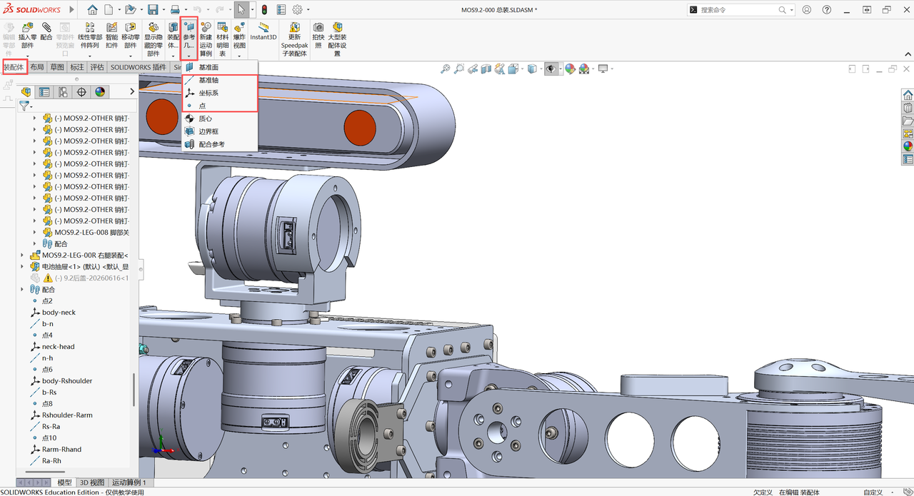
Select a point: choose the center of a face, then select a face at the joint's rotation or translation center as the origin of the coordinate system.
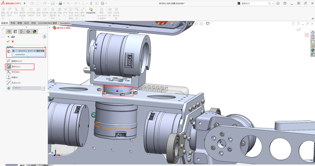
Then create the coordinate system:
First select the origin: choose the Point created in the previous step. Then define the Z-axis: it must align with the joint's rotation axis or translation axis. This is required by the URDF standard: revolute joints rotate about the Z-axis, and prismatic joints move along the Z-axis.
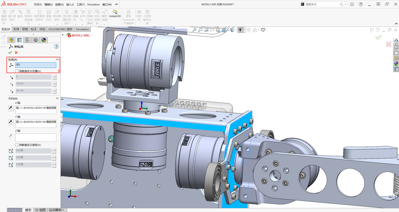
Reference axis: choose the Z-axis of the Coordinate System created in the previous step. The export plugin will use this to define the joint axis.
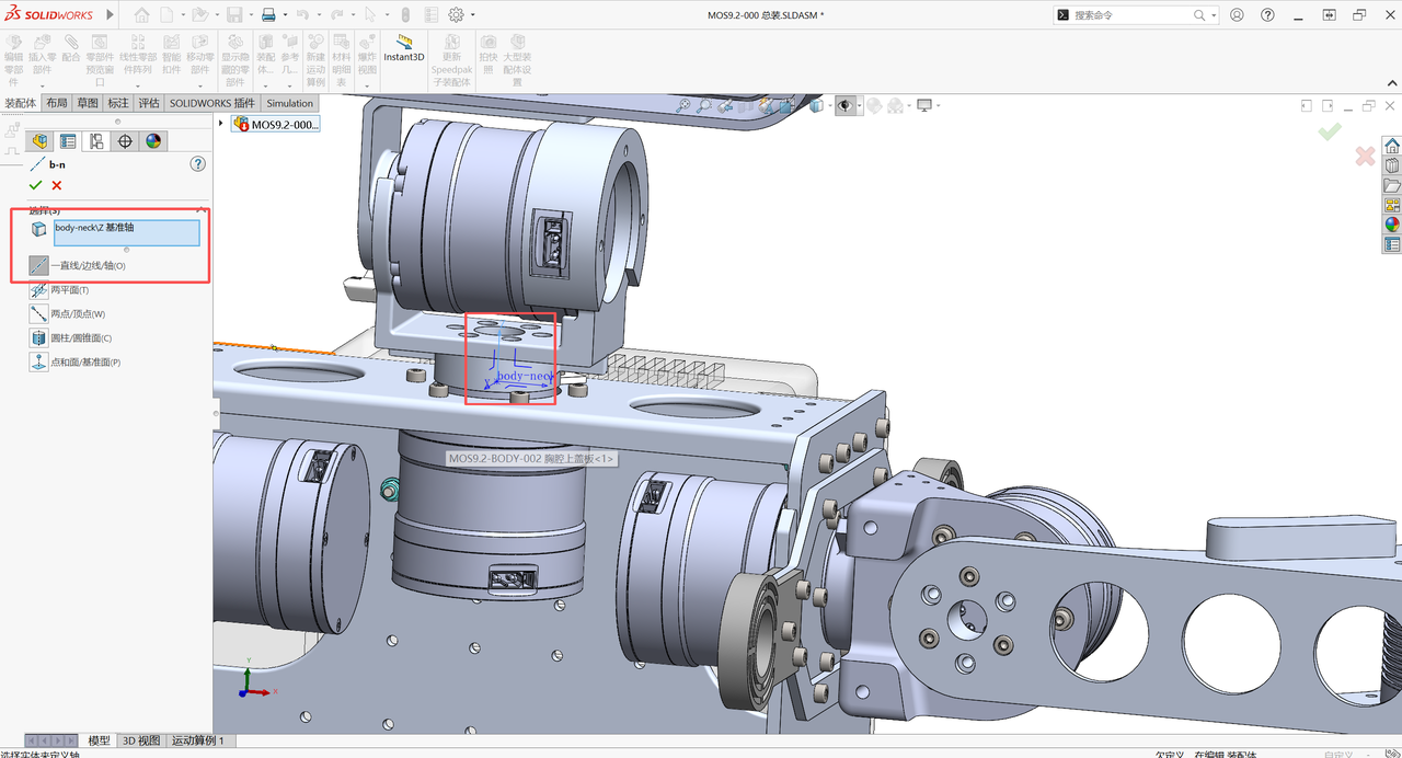
Naming convention: use clear and consistent names for all created reference geometry.
Step 3: Configure the URDF Export Plugin
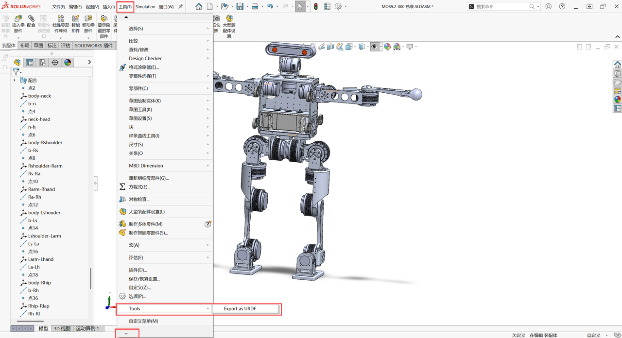
Launch the plugin: in SolidWorks, click Tools -> Export as URDF.
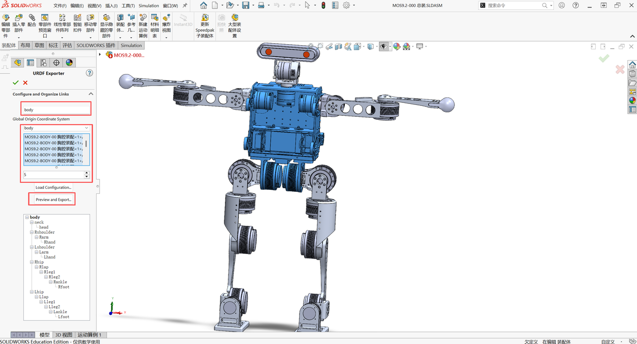
Define the Base Link:
- Link Name: name the robot base, for example base_link.
- Coordinate System: select the robot's overall reference coordinate system, usually the world coordinate system or the base center.
- Parts: select all parts that are stationary relative to the base.
- Children: fill in the number of branches extending from the base. For example, for a dual-arm robot whose base connects to the head, left arm, and right arm, the number is 3.
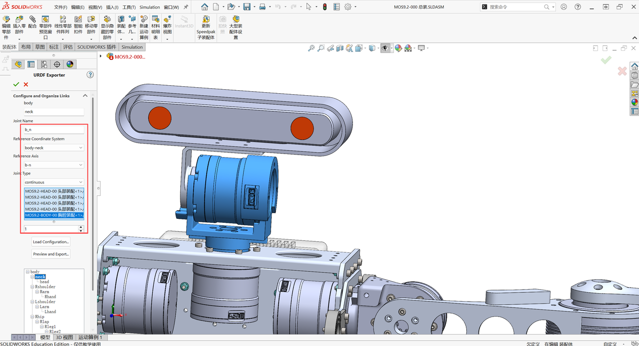
Configure each link and joint:
Following the tree structure, configure each branch one by one.
- Link Name: name the current link, for example neck.
- Reference Coordinate System: select the Coordinate System created for this joint in Step 2.
- Joint Name: name the joint, for example neck_joint.
- Joint Type: select the joint type: revolute, continuous, prismatic, or fixed.
- Axis: select the Reference Axis created for this joint in Step 2.
Repeat this step until all links and joints have been configured.
Step 4: Inspect and Correct Physical Properties
Important note: this step can be performed before or after opening the export plugin, but it is strongly recommended to complete it before exporting.
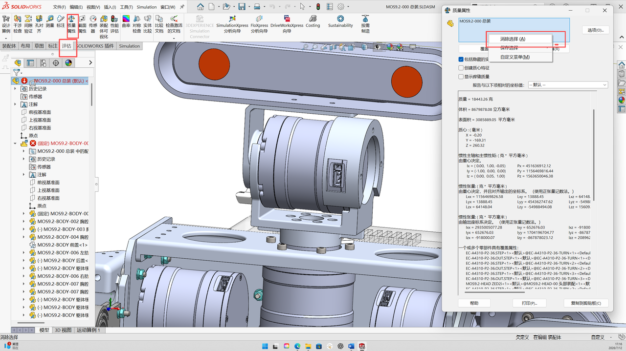
Compute mass properties for a single link:
- In SolidWorks, deselect all parts.
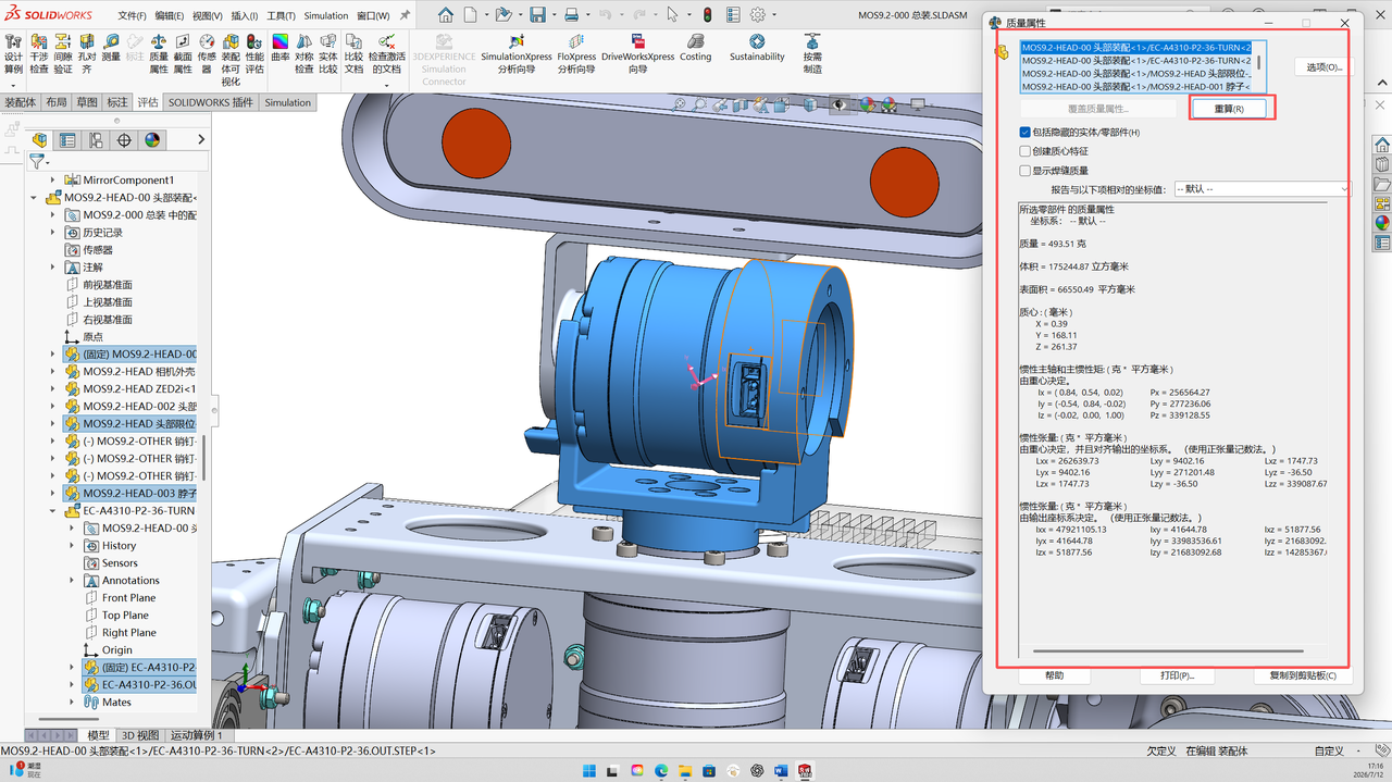
- In the design tree on the left or in the graphics area, select only the parts that make up one link, for example neck.
- Click Mass Properties under the Evaluate tab.
- Click Recompute.
- Record and fill in the data:
- In the pop-up window, record the Mass, Center of Mass, and Moments of Inertia or inertia tensor.
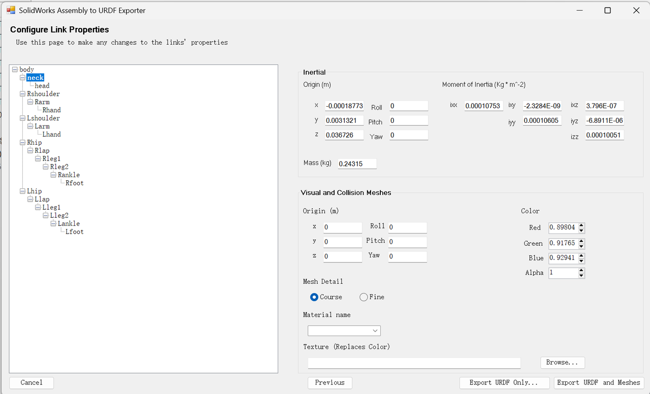
- Go back to the Configure Link Properties page in the URDF export plugin and manually enter the recorded data into the property fields for the corresponding link.
- Pay attention to units: make sure the units are consistent, usually kg and m.
Step 5: Preview and Export
- Preview: click the Preview and Export button.
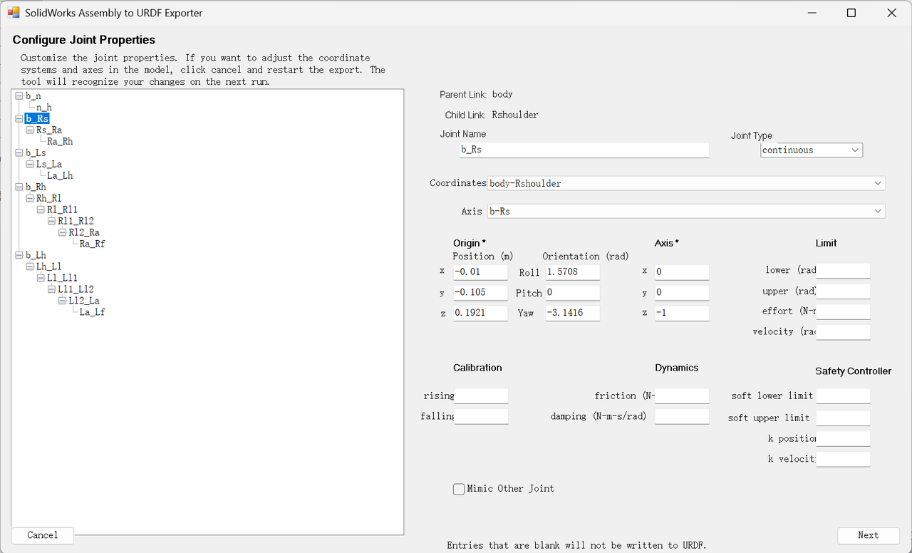
- Check joint properties:
- In the pop-up window, you can check each joint's coordinate system, axis direction, and type again.
- You can set Limits for revolute joints, including position, velocity, and torque limits.
- Check link properties:
- Confirm each link's mass, center of mass, and inertia matrix once more.
- Export:
- Click Export URDF and Meshes.
Modifying Collision Geometry
In robot simulators, the robot rigid-body model is represented by meshes, and a mesh is a 3D surface model made of many small triangles. The detailed model exported from SolidWorks contains a large number of triangles, which makes simulation very slow. For that reason, after export people usually modify the collision geometry, replacing the original complex mesh with simplified, simulation-friendly geometry such as boxes, cylinders, or spheres. In practice, simplifying collision geometry usually has little impact on Sim2Real controller performance.
To modify collision geometry or joint limits, you can use URDF Studio or a VS Code plugin.
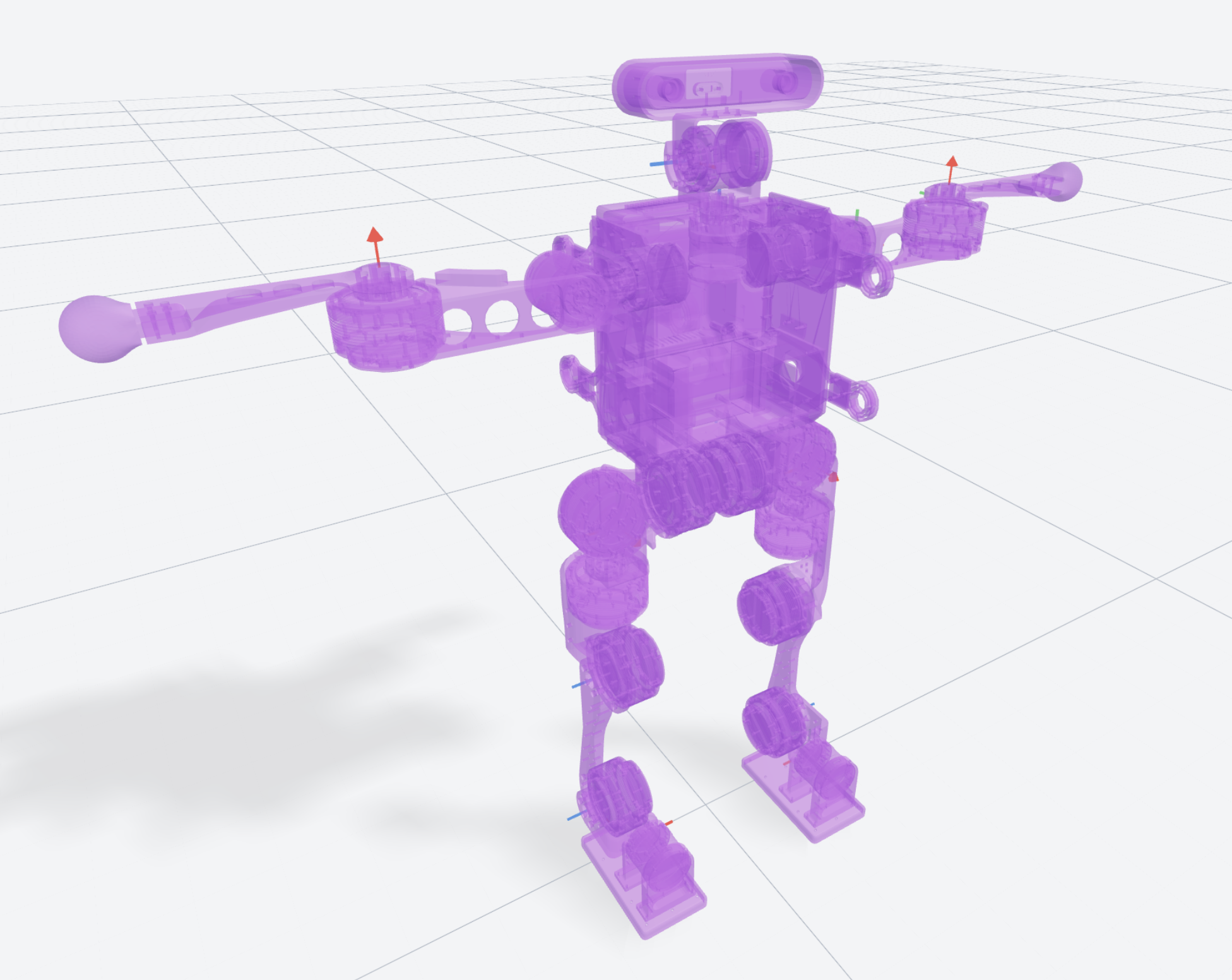
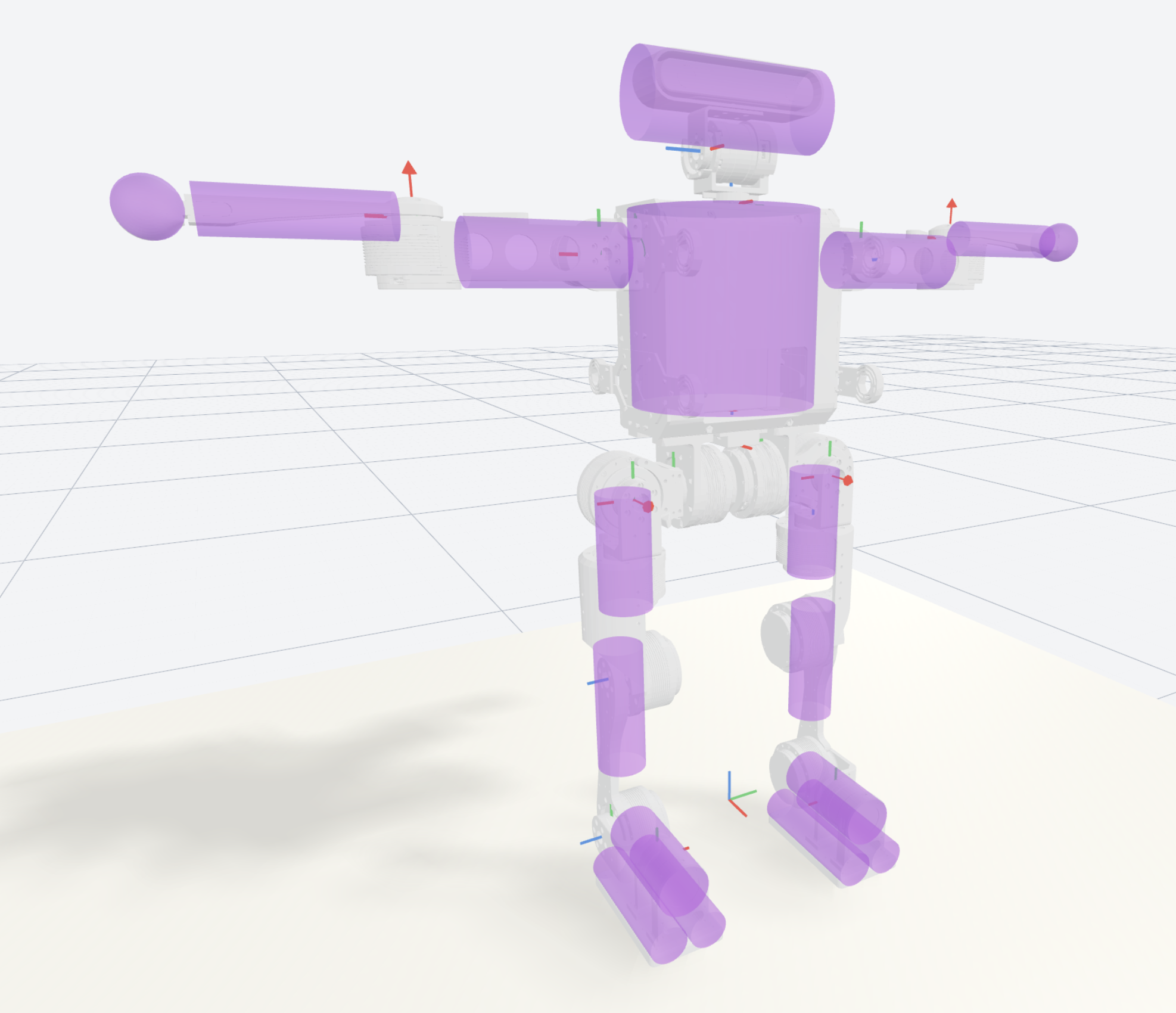
The torso, arms, thighs, and lower legs can be directly approximated using cylinders of roughly matching size. Parts that collide with the ground need more careful design, especially the collision geometry on the sole of the foot. There are several common ways to handle foot collisions: parallel cylinders, a box, or a four-point foot. Here we use parallel cylinders. Their collision behavior is similar to the previous flat-foot collision body and can preserve simulation accuracy.
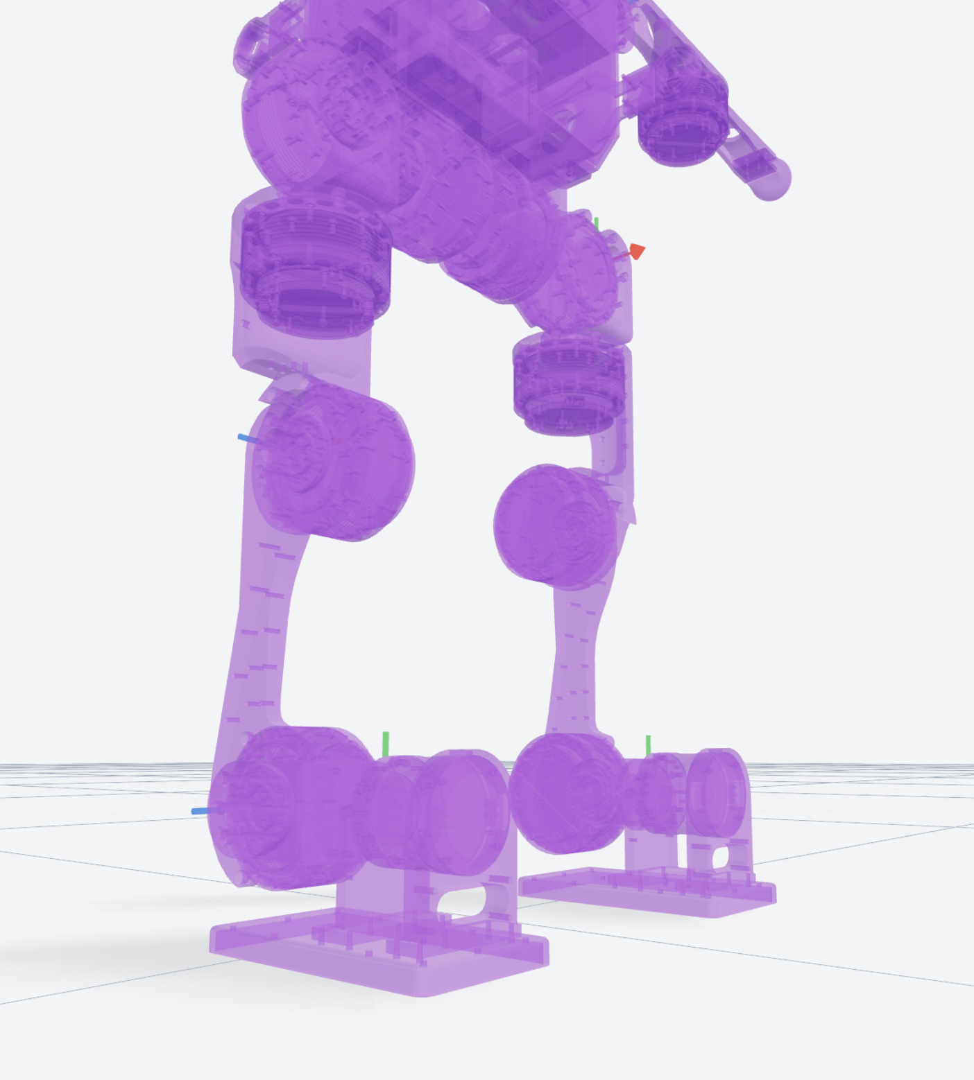
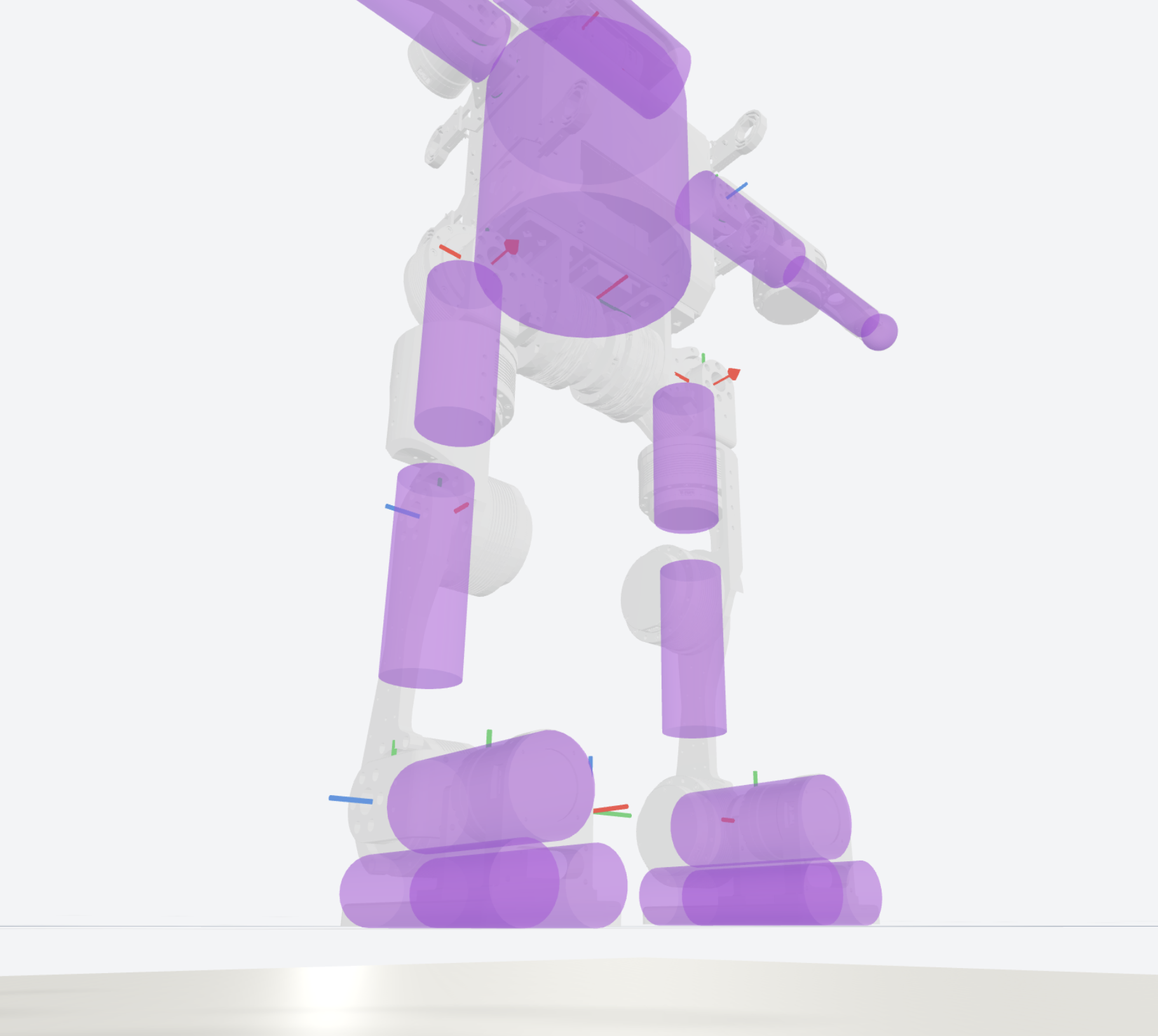
For example, the following code replaces the original mesh-based foot collision body with a three-cylinder collision body:
<link name="Rfoot">
    <inertial>
        <origin xyz="0 -0.0233 0.02403" rpy="0 0 0" />
        <mass value="0.67876" />
        <inertia
            ixx="0.00137339124"
            ixy="-2.033E-08"
            ixz="-1.7E-10"
            iyy="0.00101905647"
            iyz="-0.0002676393"
            izz="0.00088815706" />
    </inertial>

    <visual>
        <origin xyz="0 0 0" rpy="0 0 0" />
        <geometry>
            <mesh filename="../meshes/Rfoot.STL" />
        </geometry>
        <material name="">
            <color rgba="1 1 1 1" />
        </material>
    </visual>

    <!-- Collision body before modification
    <collision>
        <geometry>
            <mesh filename="../meshes/Rfoot.STL" />
        </geometry>
    </collision>
    -->

    <!-- Collision body after modification -->
    <collision>
        <origin xyz="0 0 0" rpy="0 0 0" />
        <geometry>
            <cylinder radius="0.03" length="0.13" />
        </geometry>
    </collision>

    <collision>
        <origin xyz="0.024 -0.052 -0.005" rpy="0 0 0" />
        <geometry>
            <cylinder radius="0.022" length="0.16" />
        </geometry>
    </collision>

    <collision>
        <origin xyz="-0.024 -0.052 -0.005" rpy="0 0 0" />
        <geometry>
            <cylinder radius="0.022" length="0.16" />
        </geometry>
    </collision>
</link>
Modifying Joint Limits
View the full collision model in URDF Studio, rotate each joint, and then read out the maximum rotation position and write it back into the URDF.
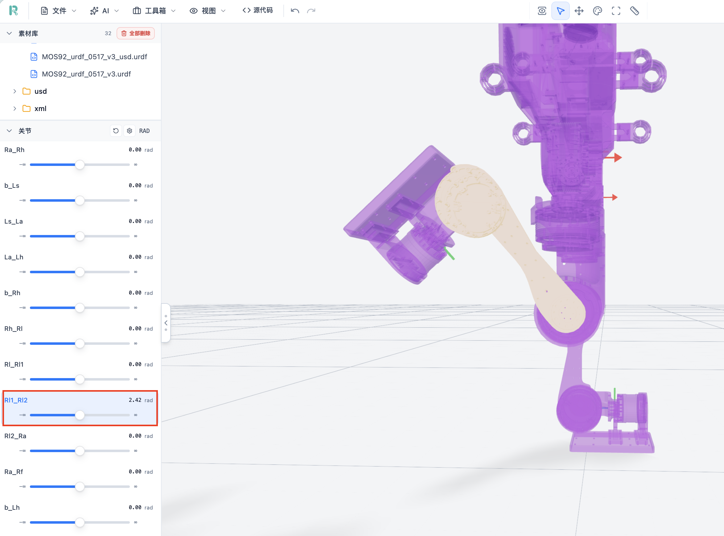
Write the joint limits into the URDF:
<joint name="right_knee" type="revolute">
        <origin xyz="-0.00900000000000004 0 -0.146"
                        rpy="1.5707963267949 0 -1.5707963267949" />
        <parent link="Rleg1" />
        <child link="Rleg2" />
        <axis xyz="0 0 -1" />
        <limit lower="-1.0" upper="2.3" />
</joint>
Although the figure shows that a maximum position of 2.42 could also work, we use a stricter limit and set the maximum position to 2.3. This can be adjusted freely according to your needs.