Structural Component Design
This section introduces the structural component design of the robot.
Overall Approach
The overall configuration was finalized in the previous section. From here, there are essentially two main questions to solve: how to design the connecting parts so that the joints retain sufficient range of motion, and where to place the control boards, communication boards, and onboard computer. Once these issues are handled properly, the robot design is basically complete. Below we present the design approach used for MOS9 as a reference.
Chest Design
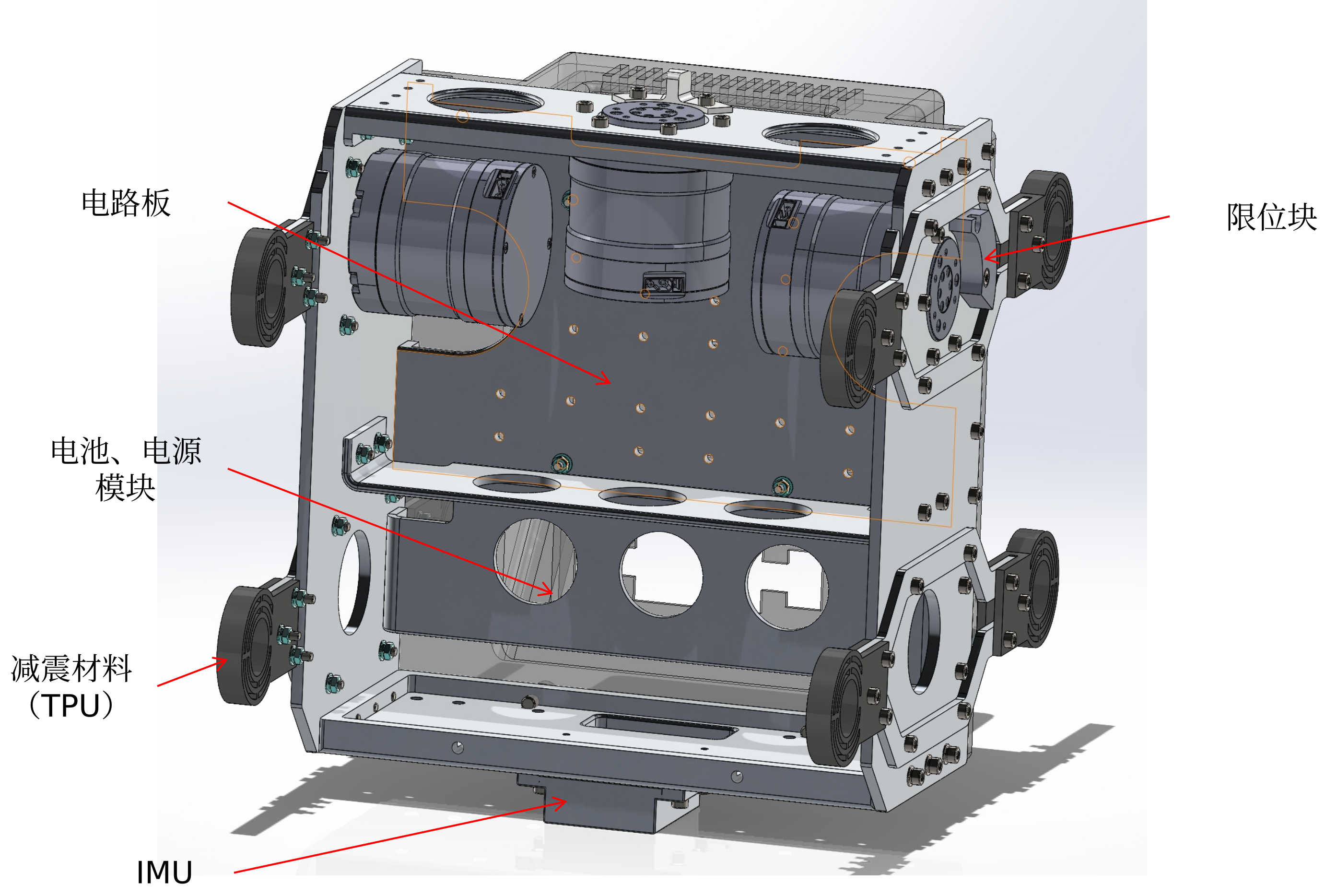
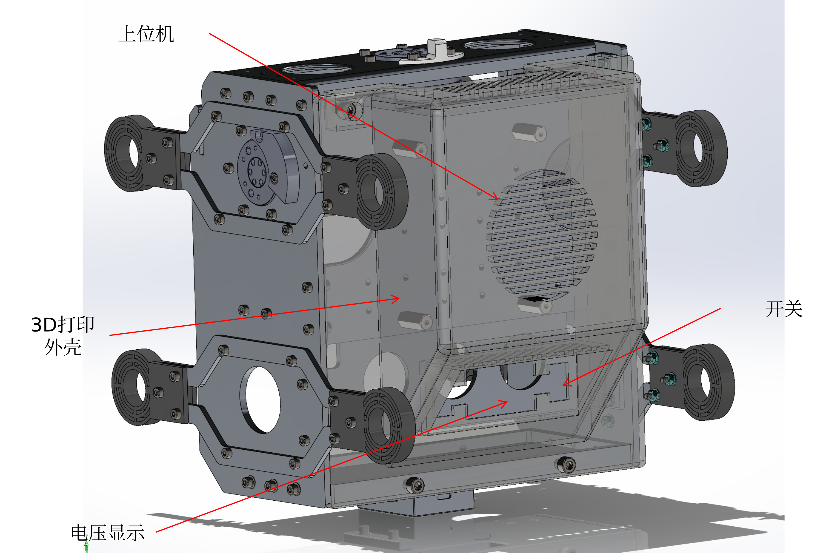
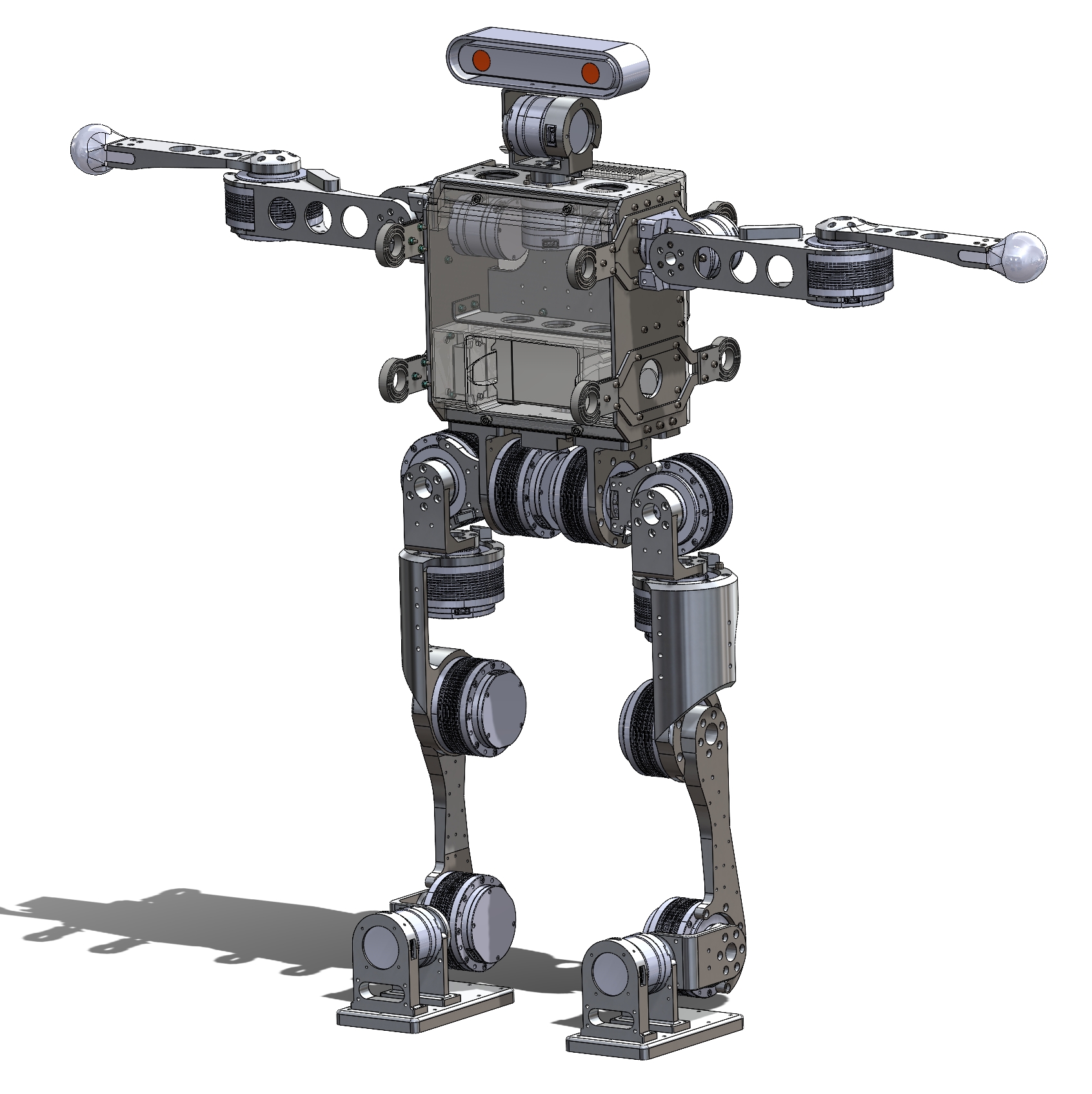
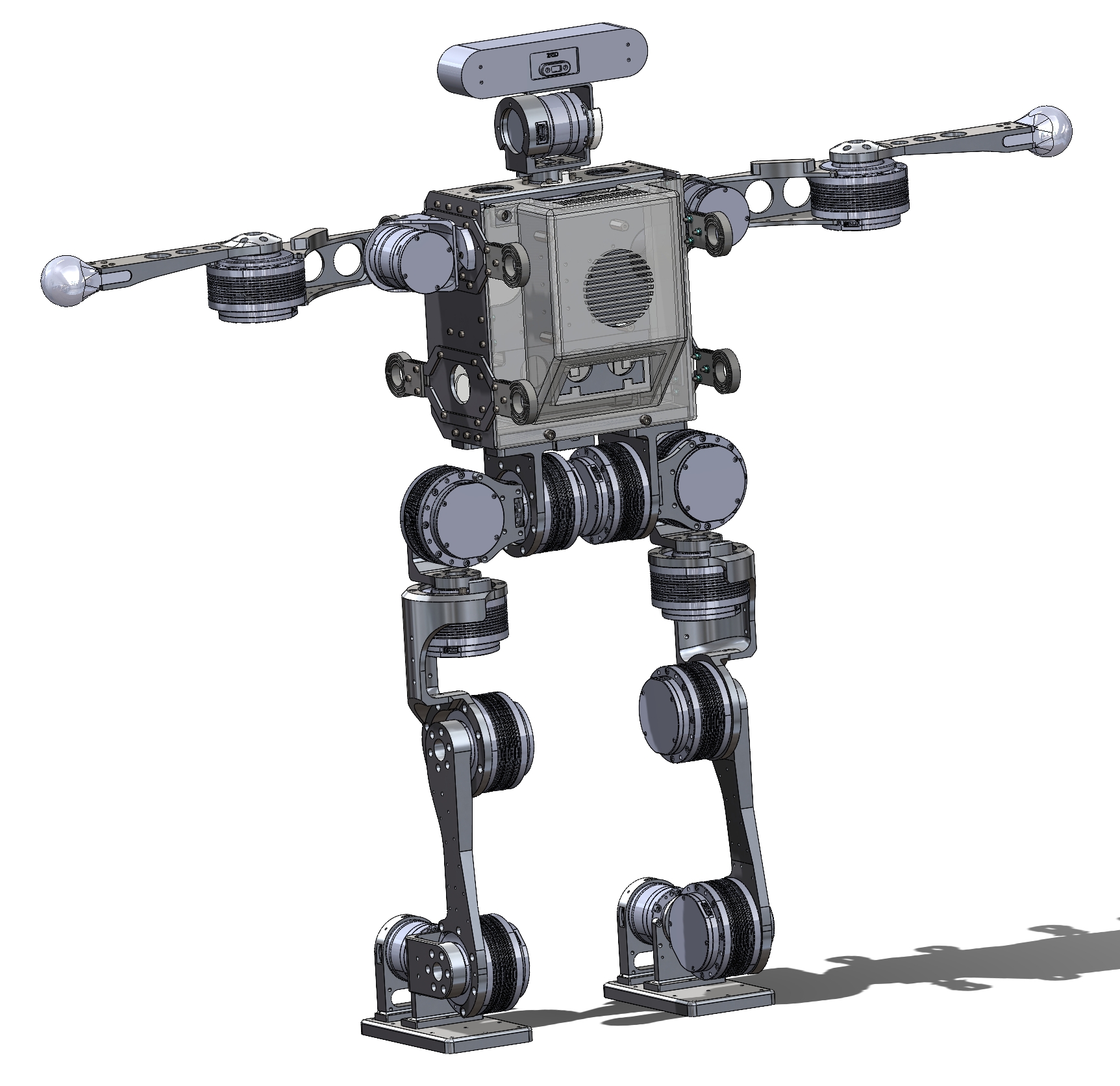
The chest mainly focuses on the arrangement of the battery, control boards, and onboard computer. We divide the chest into two halves, front and rear. The front half is used for electronics, while the rear half holds the onboard computer. In the front half, the circuit boards are placed above and the battery is placed below. Both the front and rear shells are 3D-printed parts to reduce weight. Ventilation holes and cable-routing holes are added to the rear shell, while the power switch and voltage display are placed underneath it for convenient battery monitoring. We also added TPU shock-absorbing material to reduce impact when the robot falls.
Leg Design
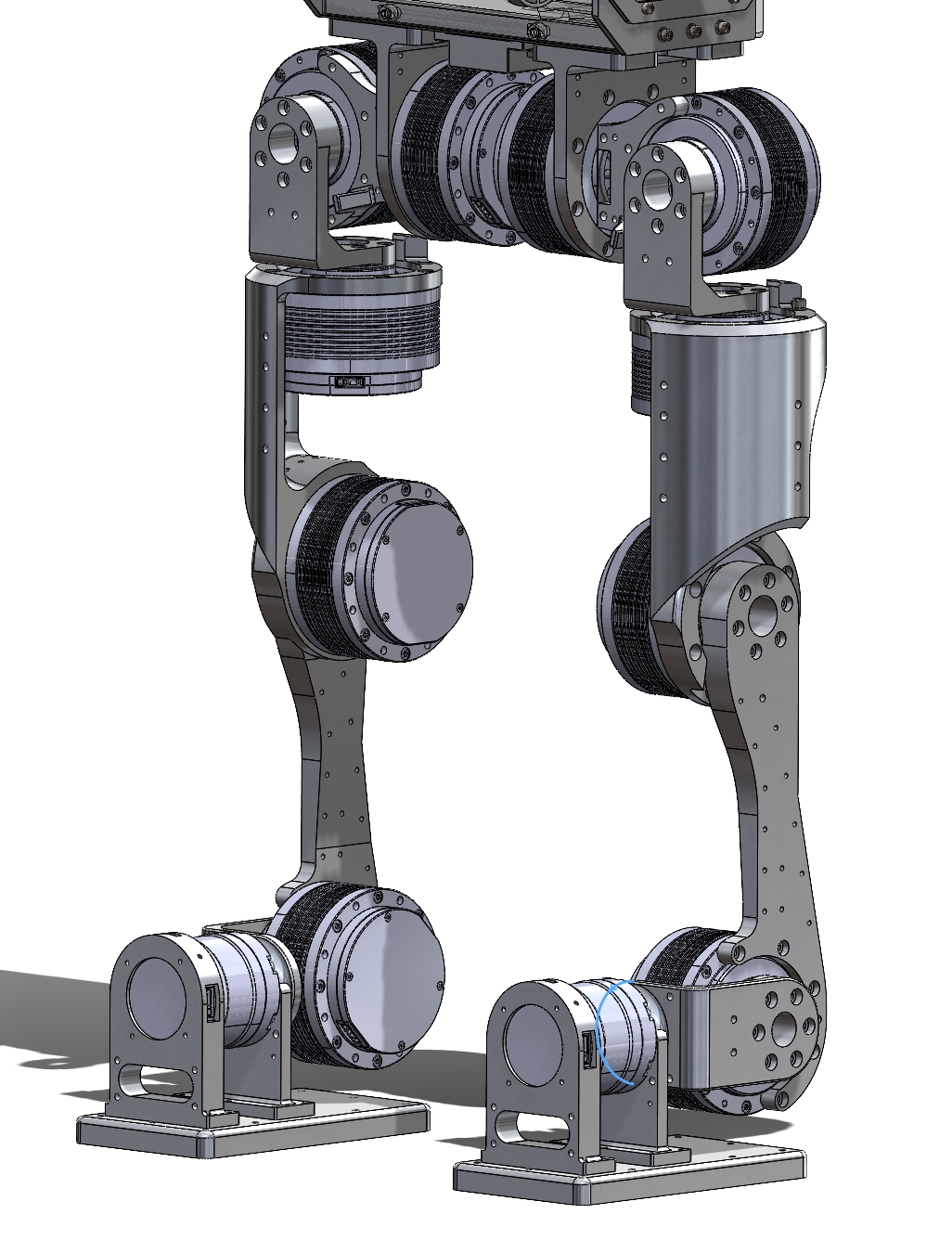
The legs, arms, and head are all serial chains of degrees of freedom, so the main requirement is simply to connect the motors properly through the links. This part of the design is relatively flexible. The main concerns are structural strength, weight, and other detailed engineering tradeoffs.
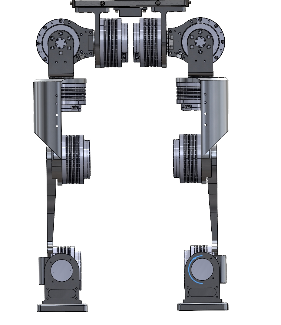
Since ENCOS motors are mounted from one side, the rotor connectors we designed are also single-sided. A double-sided rotor connection would require an additional bearing on the other side of the motor, which would increase assembly complexity. For aluminum alloy parts, a thickened single-sided connector provides roughly the same strength as a double-sided one, so we adopted the single-sided design throughout. This can be seen more clearly in the side view.
Overall Drawings
Other specific details can be examined by opening the SolidWorks drawings.
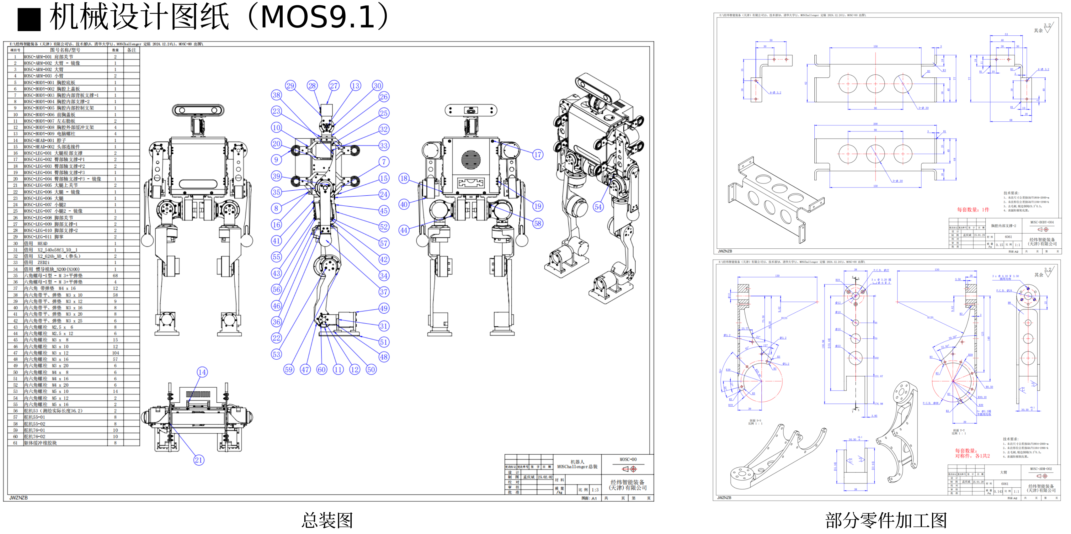
When building MOS9.1, we worked with a manufacturer to prepare 2D drawings and machining, so we produced a complete set of 2D drawings. Later, for MOS9.2, we used JLC CNC, so we did not prepare a full 2D drawing set. Only parts with threaded holes were given 2D drawings. Some of those drawings are shown below for reference.